

Application
Drill patterns, borehole spacing and drilling depth
Correct borehole arrangement is one of the most important factors for successful use of BETONAMIT®. Spacing, row arrangement and depth determine the crack pattern and splitting effect.
- Maximum hole spacing
- about 10 × borehole diameter
- Starting value for unknown material
- about 6–8 × borehole diameter
- First row at a free edge
- about ½ the normal spacing
- Drilling depth in blocks
- at least 75% (¾), ideally up to 100% of material height
Fundamentals
No single rule suits every material
Besides borehole diameter, the spacing, row arrangement and depth strongly influence the resulting cracks and splitting effect.
Rock, concrete, heavily reinforced concrete, exposed blocks and rock excavation all react differently. These rules are proven planning guidance rather than a universal formula.
Rule of thumb
Maximum about 10 × borehole diameter
As a general rule, the maximum spacing is approximately ten times the borehole diameter: borehole spacing ≈ maximum 10 × borehole diameter.
Example: a 40 mm hole gives a maximum of about 400 mm = 40 cm, so a 40 × 40 cm grid is a typical maximum starting point.
The 10 × rule is not optimal for every material. Smaller spacing allows neighbouring holes to interact more strongly.
Material
The correct spacing depends on the material
The optimum depends on strength, structure and reinforcement. Difficult material requires closer holes; material that splits readily may allow larger spacing.
01
Heavily reinforced concrete: about 5 × Ø
With Ø40 mm this is only about 20 cm. Reinforcement strongly affects cracking and keeps concrete segments connected.
02
Concrete and normal rock: about 6–10 × Ø
For unknown material, start conservatively at 6–8 × Ø. If it reacts very well, spacing can then be increased.
03
Soft, readily split rock: up to about 15 × Ø
At Ø40 mm this is around 60 cm. Do not use this automatically; joints, bedding, free faces and required fragment size are decisive.
04
Start conservatively
The first crack pattern quickly shows whether spacing can be increased, reducing consumption without risking the splitting effect.
Arrangement
Symmetrical or staggered drill pattern?
Symmetrical rows: holes line up horizontally and vertically. KUBATEC prefers this arrangement for most applications because pressures overlap along and between rows, producing a controlled, predictable crack pattern.
Staggered rows: each row is offset by about 50%, producing a zigzag or triangular pattern. This can create more branched cracks and smaller fragments in some materials.
In our experience, symmetrical patterns offer several advantages:
- simpler planning
- simpler setting-out
- clearer rows
- better interaction in both directions
- readily controlled crack pattern
Edge distance
The first row at a free edge
If normal spacing is S = 10 × Ø – at Ø40 mm, S = 40 cm – the first row should be only about 20 cm from the edge.
Between rows, holes act on one another. At a free edge there is no hole outside, so the first row must move that material alone.
Rule: distance to free edge ≈ ½ normal borehole spacing.
Drilling depth
Depth is at least as important as the grid
Depth determines the effective lever. The deeper a hole reaches, the larger the zone exposed to expansive pressure.
In rock benches, the lower area must also be affected. Short holes may crack the top while leaving the base connected.
The principle is: the deeper, the better. Use at least 75% (¾) of material height, ideally 100%.
For exposed foundations, boulders or blocks, drill at least 75% (¾) and, where possible, 100%. For a 1 m block, drill at least 75 cm, ideally 100 cm.
Radial pressure must be transferred through the material. Greater depth reduces the unbored base and improves leverage.
If a small foundation, slab or plinth is drilled through, close the bottom before filling with a ball of plastic, paper or newspaper or another suitable plug.
Seal every through-hole at the bottom so the slurry cannot drain out and the full charge remains in place.
Large boulders
Alternative: angled drilling
If a drill cannot reach 75% of a very large boulder, drill obliquely towards the centre from several sides, for example from two opposite faces.
This enlarges the effective zone. The pressure zones work against each other and help tear through the undrilled centre. Adapt the arrangement to stone shape and natural structure.
Free faces and fragment size
Give the material somewhere to move
BETONAMIT® generates pressure, but the material needs a direction in which to move or open. Without a free face, the following become especially important:
- closer borehole spacing
- sufficient drilling depth
- a sensible drilling sequence
- additional relief holes where required
Where no free face exists, use holes inclined at about 45 degrees, particularly in rock or shaft excavation, large foundations, bunkers and restrained elements.
Pressure always acts at 90 degrees to the borehole wall. A hole at around 45 degrees redirects part of the force upwards, creating space above.
The exact angle can be optimised for depth, access and required break direction; about 45 degrees is the practical guide.
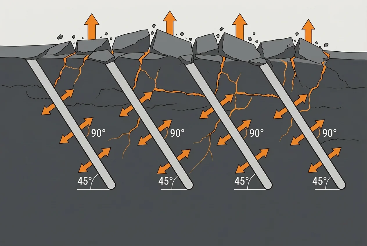
- rock and shaft excavation without a free face
- large concrete foundations, plinths and slabs
- bunkers, basements and heavily reinforced elements
- holes from the base or an already open side
- Smaller spacing produces smaller fragments; larger spacing produces larger pieces.
Guide values
Typical spacing by borehole diameter
Diameter and spacing belong together. A larger hole contains more BETONAMIT® per drilled metre and creates a larger effective zone, so spacing is expressed as a ratio to diameter.
| Ø borehole | 5 × Ø | 6 × Ø | 8 × Ø | 10 × Ø | 15 × Ø |
|---|---|---|---|---|---|
| Ø25 mm | – | 15 cm | 20 cm | 25 cm | 37.5 cm |
| Ø30 mm | – | 18 cm | 24 cm | 30 cm | 45 cm |
| Ø35 mm | – | 21 cm | 28 cm | 35 cm | 52.5 cm |
| Ø40 mm | 20 cm | 24 cm | 32 cm | 40 cm | 60 cm |
| Ø45 mm | 22.5 cm | 27 cm | 36 cm | 45 cm | 67.5 cm |
| Ø50 mm | 25 cm | 30 cm | 40 cm | 50 cm | 75 cm |
These values are guides and must be adapted to the actual material and task.
Practice
KUBATEC’s recommended procedure
01
Choose diameter
Select a suitable borehole diameter for the material and task.
02
Start conservatively
Begin with approximately 6–8 × borehole diameter.
03
Halve the edge distance
Place the first row only half the normal spacing from the free edge.
04
Drill symmetrically
Use a symmetrical grid wherever possible.
05
Drill deeply enough
In blocks and foundations drill at least 75% (¾), ideally up to 100% – the deeper, the better.
06
Seal through-holes
Plug the bottom with plastic, paper or newspaper before filling so nothing drains out.
07
Observe and optimise
Assess the first crack pattern and increase spacing gradually if the reaction is very good.
The optimum pattern combines calculation, material knowledge and practical experience. Good planning directs the enormous force of BETONAMIT® exactly where it is required.
FAQ
Frequently asked questions about drill patterns
+How far apart may boreholes be?
As a rule, no more than about ten times the borehole diameter; at Ø40 mm, around 40 cm. For unknown material, start at 6–8 × Ø.
+How far should the first row be from a free edge?
About half the normal spacing. With a 40 cm grid, use approximately 20 cm.
+How deeply should I drill into boulders or foundations?
At least 75% (¾) of the total height, ideally up to 100%. For a 1 m block, at least 75 cm, ideally 100 cm.
+What if the borehole passes through the element?
Seal it at the bottom before filling, for example with a ball of plastic, paper or newspaper, so the material cannot drain out.
+Symmetrical or staggered pattern?
KUBATEC recommends a symmetrical pattern for most applications: it is easier to plan and set out and gives predictable interaction in both directions.
Read on
Read on
Expansive mortar
How it works, how it developed, drill patterns and the limits of non-explosive splitting – explained concisely.
Alternative demolition methods
Hammer, wire saw, splitting cylinder, conventional blasting or expansive mortar: when each method pays off.
Rock excavation
Building pits, road construction, tunnel re-profiling – breaking rock without vibration and without a blasting permit.
Splitting boulders
From field stones to 50-tonne blocks: drill, fill, wait – without flying debris and without vibration.
Concrete demolition
Separating foundations, plinths and mass concrete in a controlled way indoors and in populated surroundings.
Reaction time
First cracks after 8–16 hours are only the beginning: pressure continues to rise for several days and peaks after about one week.
Business location Liechtenstein
Highly industrialised, politically and financially stable, globally connected: the location behind BETONAMIT® and ROCKSPLIT®.
Mechanical application
Mix and pump BETONAMIT by machine: tonnes instead of kilograms – process, MAI mixing pump, water setting of 1.0–1.2 litres per 5 kg and safety.
Plan the drill pattern
We help define borehole diameter, spacing and depth for your material.